I am planning to cover the tubes in a shrink wrapping material to make the project more waterproof.
Sunday, May 5, 2013
Bike Bar Lights LED test
Here is as short video that shows a test of LED strips on a bike frame.
I am planning to cover the tubes in a shrink wrapping material to make the project more waterproof.
I am planning to cover the tubes in a shrink wrapping material to make the project more waterproof.
Wednesday, February 6, 2013
Disco Bike - Radio test
This is a test of a cheap 433Mhz transmitter and reciever from SparkFun electronics. Together they cost only $7 for the pair. I did a test with two arduinos one transmitting data and the other recieving, both outputing over serial to debug. The fidelity seemed pretty good (Although it was only short range ~1m) without an antenna. This video shows a test using the musical output of the computer which is sent to an anolog pin on the arduino. The Arduino reads the voltage and sends a byte to the transmitter. The receiver on the other end then pulls that value in and is SUPPOSED to adjust the brightness of the LEDs accordingly.
Unfortunately, the signal is two noises causing the value to fluctuate wildly. The instability also means that the LEDs are on for a very short period so its difficult to see the lights change their state.
.
Unfortunately, the signal is two noises causing the value to fluctuate wildly. The instability also means that the LEDs are on for a very short period so its difficult to see the lights change their state.
.


Embedded Bike Lights + ATTiny = More Flashiness
I have been slowly working towards a mobile bike light show. The most recent step in that project has been to create a small PCB that I can place inside the wheel with an MCU that will be able to control the flashing of the lights.
I have already done several prototypes of such a board. Here is video of the different modes I have programmed in. Sorry that LEDs dont glow very brightly. I was VERY conservative with the current limiting resistor because I didn't want to risk blowing any (they would be a pain to replace). The power supply is putting out around 200mA but it could be closer to 400mA.


Sunday, February 3, 2013

Wednesday, January 23, 2013
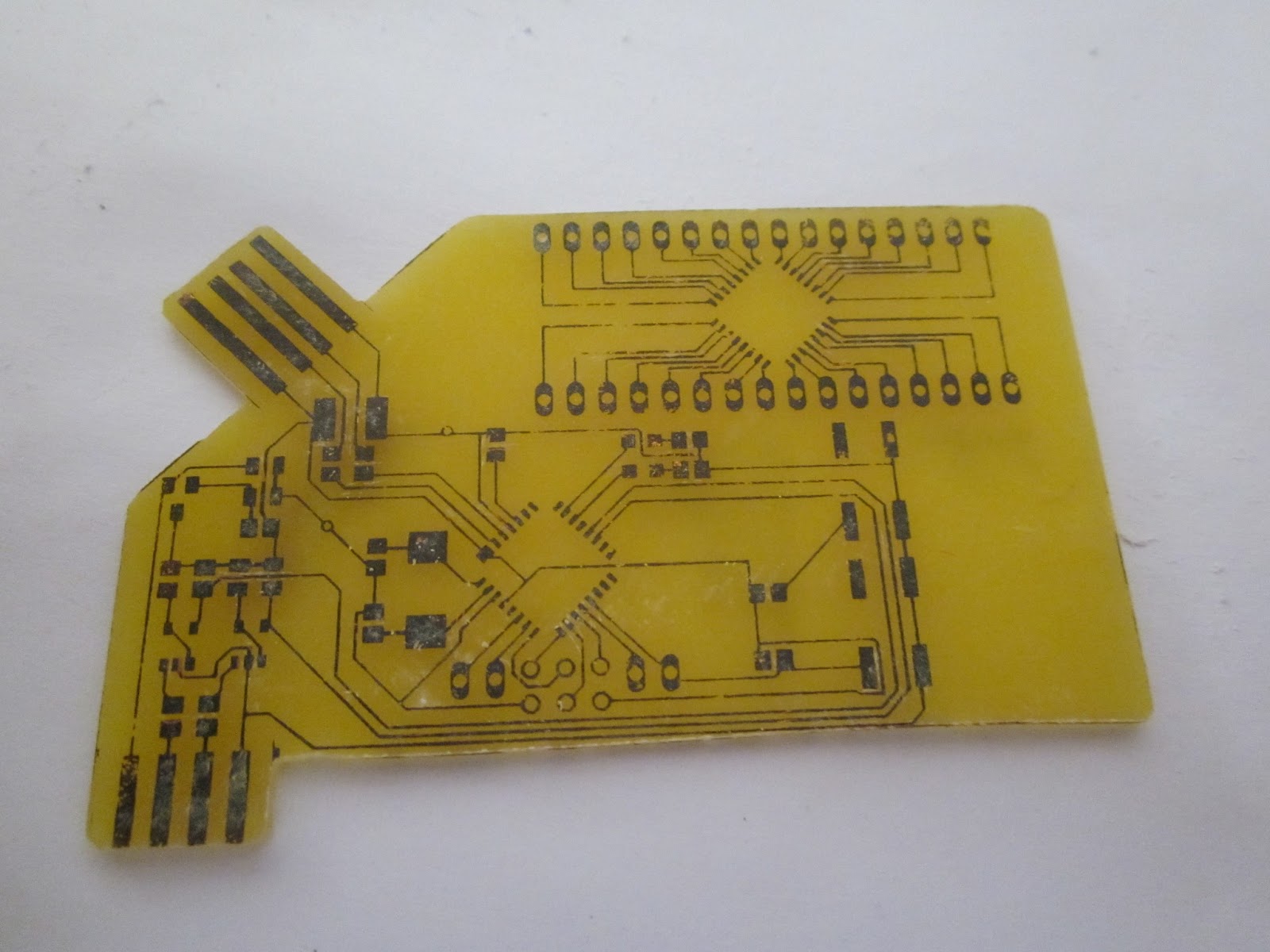
PCB Home Etching
This is my first attempt at using SMD components. It is also my first attempt at using a toner transfer method , and developing a design using EagleCAD.
I am making a circuit that reads a cheap digital caliper and outputs the values as a keyboard. to be used for CAD programs. It has also been designed to be a business card that prints out a resume.
Before I continue, I must reference the group of projects that I took ideas from in order to begin this little project.
Other Projects of inspiration

http://www.instructables.com/id/USB-PCB-Business-Card/

Increadible POV PCB Business card with full small scale circuit fab setup.
http://www.instructables.com/id/Circuit-Board-Lab-POV-Business-Card/#intro

http://www.nerdkits.com/videos/digital_calipers_dro/
Benito USB to serial
http://dorkbotpdx.org/blog/feurig/build_your_own_usb_to_serial_device
PCB etching youtube tutorials by Anomus:
http://www.youtube.com/watch?v=di5WD7AhVzI
Anomus' blog:
http://aonomus.wordpress.com/
Build Log
 |
| These are the parts that arrived from digikey |
 |
| Board after rubbing off carrier paper and prior to etching |
 |
| After the first attempt at etching - note the white areas where papaer remains inbetween busy areas. |
 |
| After the toner transfer - looks good, some patchy parts. Particularly some of the traces for the breakout did not transfer properly (center top). |
 |
Frank Zhao notes in his build that a USB connector is 2.3mm and the standard PCB is 16mm therefore some kind of packing is required on the PCB to elevate the pads and make contact with the USB connector.
|

 |
| Final shape cutout |
 |
The PCB had to be filed to get it thin enough to fit into the slot on the caliper. I also guestimated the pitch wrong. I will need to fix that in the next revision.
|
 |
| Tinned the connectors to make them more durable. |
 |
| The final board except for the ICs |
 |
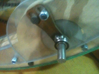
The adjustment nut on the caliper conflicts with the header pins. Should have seen that one coming. I will fix that in the next revision.
|
Lessons learnt and improvements for next design.
Design
- Increase DRC minimum spacing from 8mil to 16mil
- Change trace widths to:
- 10mil where passing under components
- 15mil inbetween
- 20mil where space allows\
- Move quad pack back and up to make more room for programming pins
- Adjust caliper tab spacings
- Make pads bigger on ISP 6 pin stack
- Round/fillet corners on the card
- Join USB and caliper connectors
- Adjust caliper outside dimension
- improve ground via for left side
Construction
- More time/heat/pressure to transfer the toner
- more spent removing excess paper after transfer.
- Remember to touch up bad parts with sharpie.
- better control of temperature and dosing.
Sunday, January 20, 2013
A Bakfiets Design
Bakfiets bikes are really cool. They are also really expensive and rare here in Australia. An importer sells these bikes from between $3000 to over $4000 for a motorised version.


http://dutchcargobike.com.au/azor-bike-bakfiets-cargo-bike-classic/
Instructables have a few builds for a Bakfiets style bike
Based on what I have read on the internet, I made up these basic specs for my design:
- The bike needs to be electric - to cope with the large hills of Brisbane and increased weight.
- Disc braking will be required - I have read that caliper rim brakes do not have the stopping force required for these bikes when carrying a burden on a hill.
- The rear wheel will be a 26'' Mountain Bike wheel - as these wheels are more robust and have provision for disc brakes.
- The front wheel will be a 20'' BMX Bike wheel - Need MTB hub with disc brake.
- RHS steel box section for the base - I would like this to be a 'jig' for the rest of the bike. ie. the RHS will extend beyond its final position to help support the forming of the other components of the bike. Specifically, dummy hubs will be mounted to temporarly mount the chain stays and front forks will components are aligned and welded. The excess can then be cut off later.
Hand sketch to give some dimensions based mostly on my current bike to give a starting off point. Some notes about design constraints:
- Main RHS bottom tube and top tube are parallel to eachother and the ground (for ease of design)
- the angle to the horizon of the seat and steering tube is 75deg because this is a nice round number :D.
- the seat and steering tube are 500mm apart as this is roughly what I have now and thats comfortable.
- The box will need support underneathe to stabilise the load and stop the box from twisting loose.
- The steering tube will need a bash guard (10mm rod steel) to protect it.

I drafted the bike in sketchup to get a more scale idea of what it might look like.

More work to be done!
Bike Restoration
Update: (Nearly) finished bike
 +
+
= +
+
 +
+
A $40 and a $30 bike put together to make a solid bike worth more than the sum of its parts ($70). And plenty of spares for the next one!
Build Log.
Weekend project #91231 fix up a old vintage bicycle for my girlfriend to make her uni commute a little easier.Surfing eBay for a while I came upon, bidded and won this 10 speed Reighliegh bike for $39.
Of course, the advert said that this bike was suitable for people over 170cms tall. I thought my girlfiend was that tall. Turns out she isnt. not even close. She is only 160cms tall. I allways get my 60s and 70 mixed up! they sound so alike. When we got it homr she jumped on and had a little ride with a bit of difficulty. Even though we lower the seat fully she had trouble reaching the brakes and touching the ground without standing over the top tube and not in the saddle. I will have to configure the bike wherever possible to make it suitable to her height.

Step 1 - Stripping down the bike.
 We pulled the bicycle completly apart seperating all the assemblies into small containers to keep the bits together. I threw out the old cables which were rusty and stiff.
 We gave all parts a hit with the degreaser before a soapy bath to clean off all that mucky grease with bits of sand and grit suspended in it.
  Overhauling the hubs. All the ball bearings were removed and the hubs were degreased. I plan to buy some replacement balls for the hubs. The balls we have are a little worn. I think they are relatively cheap. I called Allied BEarings that quoted around $5 for 100 1/4'' balls. I am going to buy a bunch so I can service other bikes in the future.
Here is a photo of the frame stripped down before repainting. I am sorry that I didnt take more photos.


The painted bike ready for reassembly forks, handlebars, and seat fitted. We used two coats of primer and 3-4 coats of silver top coat. I wish my girlfroiend had agreed to a different colour. The before and after photos wont be as impressive.

Note that we did a chop and flip on the old drop bars to make bull horn handlebars (I think that was my influence working away). However, in this configuration my girlfriend was too bent over to reach the bars comfortable. So it became a chop flip and rotate. I like it!
With the newer sealed bearing (Shimano BR26) which replaced an old ball bearing bracket, because the bearing is much shorter, the chain ring is much closer to frame the inner ring hits agaist the chain stay.

Another problem! the old pull brakes have much longer calipers than modern 50mm drop brakes (around 65mm). This means that new breaks dont reach the rim side wall where they are supposed to.
I tried a fork that I have from another bike. The forks aren't as long and the brake fits fine. Unfortunately the thread on the fork is not long enough so another modification is required. You can see in the photo below that the silver (original) for is about 15mm longer than the donated white fork.


- Use the old pull brakes - I hate these because they are so fiddly. But with new shoes they should be reasonably effective.
- Buy new calilper brakes with longer drops - I was planning to buy new brakes anyway, but I wanted to get standard ones that I could share across other bikes.
- Use the white fork and cut the thread further - On the positive side, I get an excuse to buy more tools and learn a new skill, but I have to give up the forks from the other bike.
More later!
Tuesday, January 15, 2013
Arduino Shield - Stepper Driver and Digital Caliper Reader ver.3
This is my 3rd full revision of a board I am making for another project. I thought I should post the schematic/layout incase anyone else finds it useful. I am getting faster at this layout stuff. The first was so painful but I am starting to get the strategy down.

The board uses an H bridge to drive a small stepper motor. The power for the stepper is fed of the Vin pin of the arduino. So to run this you will need a 9-12v power supply feeding into the Arduino barrel jack. I have made capacity for two calipers (To measure X and Y simultaneously).
Design is based on the schematic at http://arduino.cc/en/Reference/StepperBipolarCircuit and the Nerd kit DRO tutorial. http://www.nerdkits.com/videos/digital_calipers_dro/
Check out those sites for backround reading and code.
Check back here later for build photos and my code.
Check back here much later to see the circuit in a useful application.
https://docs.google.com/file/d/0B8_hXvCtBTMMUXVFQWN4RkVTQkE/edit
Thursday, January 10, 2013
The Engineering Commons Podcast
Chris Gammell of 'the amp hour' podcast has another podcast called 'the engineering commons podcast' available at: http://theengineeringcommons.com/
The show is not focused on the electronics industry but engineering as a discipline in general.
The show is not focused on the electronics industry but engineering as a discipline in general.
Monday, January 7, 2013
CS50 - Introduction to computer science atStanford
While I was cruising youtube for tutorials on programming I stumbled across some videos for an introductory computer science class at Stanford University. It turned out that the entire course is available online for free.
 The Course is stanfords flagship unt for their faculty of computer sciences. And, because of the high status of the course and importance to Stanford as a marketing tool, you can see that they have put a lot of effort into the course (they have their own merch).
Course is available at CS50.net
https://www.cs50.net/
The lecturers are really entertaining I watched all 24 one and a half hour lectures in a few weeks. Although, I still havent got through the tutorials :D
I will be sure to [ost my solutions when/if I do them.
Course is available at CS50.net
https://www.cs50.net/
The lecturers are really entertaining I watched all 24 one and a half hour lectures in a few weeks. Although, I still havent got through the tutorials :D
I will be sure to [ost my solutions when/if I do them.
Rolling motor mono cycle is a certain death-trap
If the builder doesn't already have brain damage his invention should soon correct that.


Adafruit GPS shield

http://www.everytrail.com/view_trip.php?trip_id=1927731
http://www.gpsvisualizer.com/ is another site that does the same thing.
What I dont like about the module is that you have to take out the SD card to load the data into the computer. It would be great if the data could be accessed throught the serial port. I have started writing some code that allows you to manipulate files on the SD card with some basic menus over serial. However, I am having trouble erasing files. If you have any tips, please let me know.
I also want to add some triggering options to the GPS module. I want to do this to A) reduce power consumption B) reduce data density.
The plan is:
A mode switch allow you to select. 1.trigger mode (push button/external trigger ie camera) 2. Normal mode, sampling at the normal rate. 3. Interval timing timing is set by a potentiometer that allows for logarithmic interval timing. The idea here is to save power where possible.
Subscribe to:
Posts (Atom)