Building and using the Popbot it was clear that it was designed by an electrical engineer. the construction is really quite clumsy. Here is a list of issues I have with the design:
- Gearboxes and standoffs to give the robot its main structure.
- It also stacks the batteries over the electronics, which makes changing batteries fiddly work.
- The kit includes a servo for steering and sweeping an infrared rangefinding sensor. To mount the servo a 40mm standoff is screwed into the base.
- The kit also contains an LCD screen for giving feedback directly from the unit. The holes in the PCB of the LCD do not match the hole spacing in the mounting plate.
- The box that the kit comes in is not an appropriate shape to store the completed robot. I broke/pulled some things off the robot unintentionally because of this.
- There are several mounting holes in the gear box but few of them are aligned with the mounting plate
- The plastic box for the batteries and electronics has various other holes and cut outs like it was designed for another product and then repurposed for the robot.
- ...I will be sure to add more if it occurs to me.
Redesign:
With these complaints in mind I redesigned the structure. the model is located here in the sketchup 3d warehouse. This is the first revision and I plan to do at least a second. Stay tuned for updates.
Just finished the 2nd revision. The files are available at thingiverse.
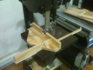
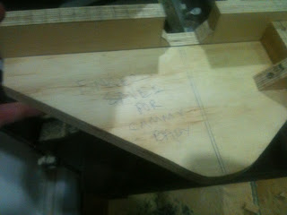
Here are some photos of the second cut revisión of the improved bot Note from the photos that there are still a fex things to do.
I still have to by a 2 x2 AA battery holder and install it. I also need to by the hardware for the bearing "whee"
You may notice from the photo that the front part does not have a bearing installed. Thats because I miss measured the wheel diameter and twith 2 bearing wheels the driving wheels were left elevated above the ground surface.
As most of the weight is the back 3 wheels will do. In the next revisión I will include a better skid in front to prevent the bot from tipping forward.
Further design improvements:
-adjust motor mounting holes to better suit the gearboxes.
-holes for servo motor mounting screws
-through holes for cable management
-A shrowd for the LCD screen
-A flexible skirt for the bot that increases the colisión sensors effective área.
-better access to the communications port.
-remove the wheel enclosing part of the upper disk.


