I am planning to cover the tubes in a shrink wrapping material to make the project more waterproof.
Sunday, May 5, 2013
Bike Bar Lights LED test
Here is as short video that shows a test of LED strips on a bike frame.
I am planning to cover the tubes in a shrink wrapping material to make the project more waterproof.
I am planning to cover the tubes in a shrink wrapping material to make the project more waterproof.

Wednesday, February 6, 2013
Disco Bike - Radio test
This is a test of a cheap 433Mhz transmitter and reciever from SparkFun electronics. Together they cost only $7 for the pair. I did a test with two arduinos one transmitting data and the other recieving, both outputing over serial to debug. The fidelity seemed pretty good (Although it was only short range ~1m) without an antenna. This video shows a test using the musical output of the computer which is sent to an anolog pin on the arduino. The Arduino reads the voltage and sends a byte to the transmitter. The receiver on the other end then pulls that value in and is SUPPOSED to adjust the brightness of the LEDs accordingly.
Unfortunately, the signal is two noises causing the value to fluctuate wildly. The instability also means that the LEDs are on for a very short period so its difficult to see the lights change their state.
.
Unfortunately, the signal is two noises causing the value to fluctuate wildly. The instability also means that the LEDs are on for a very short period so its difficult to see the lights change their state.
.


Embedded Bike Lights + ATTiny = More Flashiness
I have been slowly working towards a mobile bike light show. The most recent step in that project has been to create a small PCB that I can place inside the wheel with an MCU that will be able to control the flashing of the lights.
I have already done several prototypes of such a board. Here is video of the different modes I have programmed in. Sorry that LEDs dont glow very brightly. I was VERY conservative with the current limiting resistor because I didn't want to risk blowing any (they would be a pain to replace). The power supply is putting out around 200mA but it could be closer to 400mA.


Sunday, February 3, 2013

Wednesday, January 23, 2013
PCB Home Etching
This is my first attempt at using SMD components. It is also my first attempt at using a toner transfer method , and developing a design using EagleCAD.
I am making a circuit that reads a cheap digital caliper and outputs the values as a keyboard. to be used for CAD programs. It has also been designed to be a business card that prints out a resume.
Before I continue, I must reference the group of projects that I took ideas from in order to begin this little project.
Other Projects of inspiration

http://www.instructables.com/id/USB-PCB-Business-Card/

Increadible POV PCB Business card with full small scale circuit fab setup.
http://www.instructables.com/id/Circuit-Board-Lab-POV-Business-Card/#intro

http://www.nerdkits.com/videos/digital_calipers_dro/
Benito USB to serial
http://dorkbotpdx.org/blog/feurig/build_your_own_usb_to_serial_device
PCB etching youtube tutorials by Anomus:
http://www.youtube.com/watch?v=di5WD7AhVzI
Anomus' blog:
http://aonomus.wordpress.com/
Build Log
 |
| These are the parts that arrived from digikey |
 |
| Board after rubbing off carrier paper and prior to etching |
 |
| After the first attempt at etching - note the white areas where papaer remains inbetween busy areas. |
 |
| After the toner transfer - looks good, some patchy parts. Particularly some of the traces for the breakout did not transfer properly (center top). |
 |
Frank Zhao notes in his build that a USB connector is 2.3mm and the standard PCB is 16mm therefore some kind of packing is required on the PCB to elevate the pads and make contact with the USB connector.
|

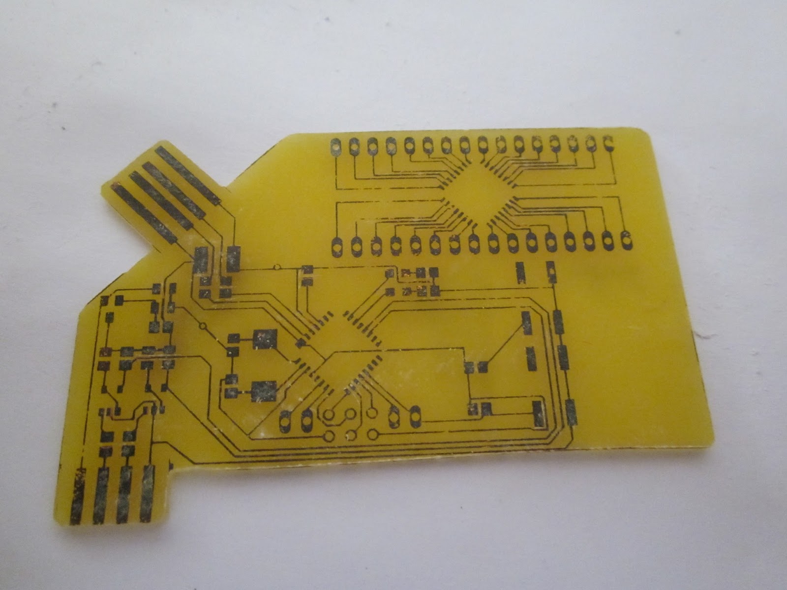 |
| Final shape cutout |
 |
The PCB had to be filed to get it thin enough to fit into the slot on the caliper. I also guestimated the pitch wrong. I will need to fix that in the next revision.
|
 |
| Tinned the connectors to make them more durable. |
 |
| The final board except for the ICs |
 |
The adjustment nut on the caliper conflicts with the header pins. Should have seen that one coming. I will fix that in the next revision.
|
Lessons learnt and improvements for next design.
Design
- Increase DRC minimum spacing from 8mil to 16mil
- Change trace widths to:
- 10mil where passing under components
- 15mil inbetween
- 20mil where space allows\
- Move quad pack back and up to make more room for programming pins
- Adjust caliper tab spacings
- Make pads bigger on ISP 6 pin stack
- Round/fillet corners on the card
- Join USB and caliper connectors
- Adjust caliper outside dimension
- improve ground via for left side
Construction
- More time/heat/pressure to transfer the toner
- more spent removing excess paper after transfer.
- Remember to touch up bad parts with sharpie.
- better control of temperature and dosing.
Subscribe to:
Posts (Atom)