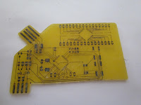
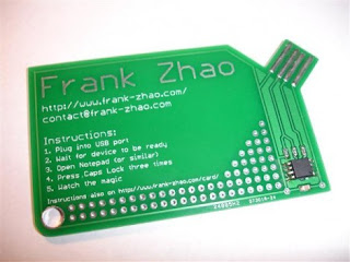
This is my first attempt at using SMD components. It is also my first attempt at using a toner transfer method , and developing a design using EagleCAD.
I am making a circuit that reads a cheap digital caliper and outputs the values as a keyboard. to be used for CAD programs. It has also been designed to be a business card that prints out a resume.
Before I continue, I must reference the group of projects that I took ideas from in order to begin this little project.
Other Projects of inspiration
USB PCB Business Card by Frank Zhao
http://www.instructables.com/id/USB-PCB-Business-Card/
Increadible POV PCB Business card with full small scale circuit fab setup.
http://www.instructables.com/id/Circuit-Board-Lab-POV-Business-Card/#intro
Nerdkits DRO the functional part
http://www.nerdkits.com/videos/digital_calipers_dro/
Benito USB to serial
http://dorkbotpdx.org/blog/feurig/build_your_own_usb_to_serial_device
PCB etching youtube tutorials by Anomus:
http://www.youtube.com/watch?v=di5WD7AhVzI
Anomus' blog:
http://aonomus.wordpress.com/
Build Log
 |
| These are the parts that arrived from digikey |
 |
| Board after rubbing off carrier paper and prior to etching |
 |
| After the first attempt at etching - note the white areas where papaer remains inbetween busy areas. |
 |
| After the toner transfer - looks good, some patchy parts. Particularly some of the traces for the breakout did not transfer properly (center top). |
 |
| Final shape cutout |
 |
The PCB had to be filed to get it thin enough to fit into the slot on the caliper. I also guestimated the pitch wrong. I will need to fix that in the next revision.
|
 |
| Tinned the connectors to make them more durable. |
 |
| The final board except for the ICs |
 |
The adjustment nut on the caliper conflicts with the header pins. Should have seen that one coming. I will fix that in the next revision.
|
Lessons learnt and improvements for next design.
Design
- Increase DRC minimum spacing from 8mil to 16mil
- Change trace widths to:
- 10mil where passing under components
- 15mil inbetween
- 20mil where space allows\
- Move quad pack back and up to make more room for programming pins
- Adjust caliper tab spacings
- Make pads bigger on ISP 6 pin stack
- Round/fillet corners on the card
- Join USB and caliper connectors
- Adjust caliper outside dimension
- improve ground via for left side
Construction
- More time/heat/pressure to transfer the toner
- more spent removing excess paper after transfer.
- Remember to touch up bad parts with sharpie.
- better control of temperature and dosing.


No comments:
Post a Comment